# Anomalous Hall Effect Measurement System
## Reference
The following paper shouold be referred to to understand the Anomalous Hall Effect:
[[1] N. Nagaosa, J. Sinova, S. Onoda, A. H. MacDonald, and N. P. Ong, “Anomalous Hall effect,” Rev. Modern Phys., vol. 82, no. 2, pp. 1539–1592, May 2010, doi: 10.1103/RevModPhys.82.1539.](https://journals.aps.org/rmp/pdf/10.1103/RevModPhys.82.1539?casa_token=mpPGv69axfkAAAAA%3AWV5ZIET03znXIYBSogCNli1TenvDDDRTfroiwmki3OnqWERgwgPfTmdVHsQyvGRj3KMGrjxBrUCKdw)
## Introduction
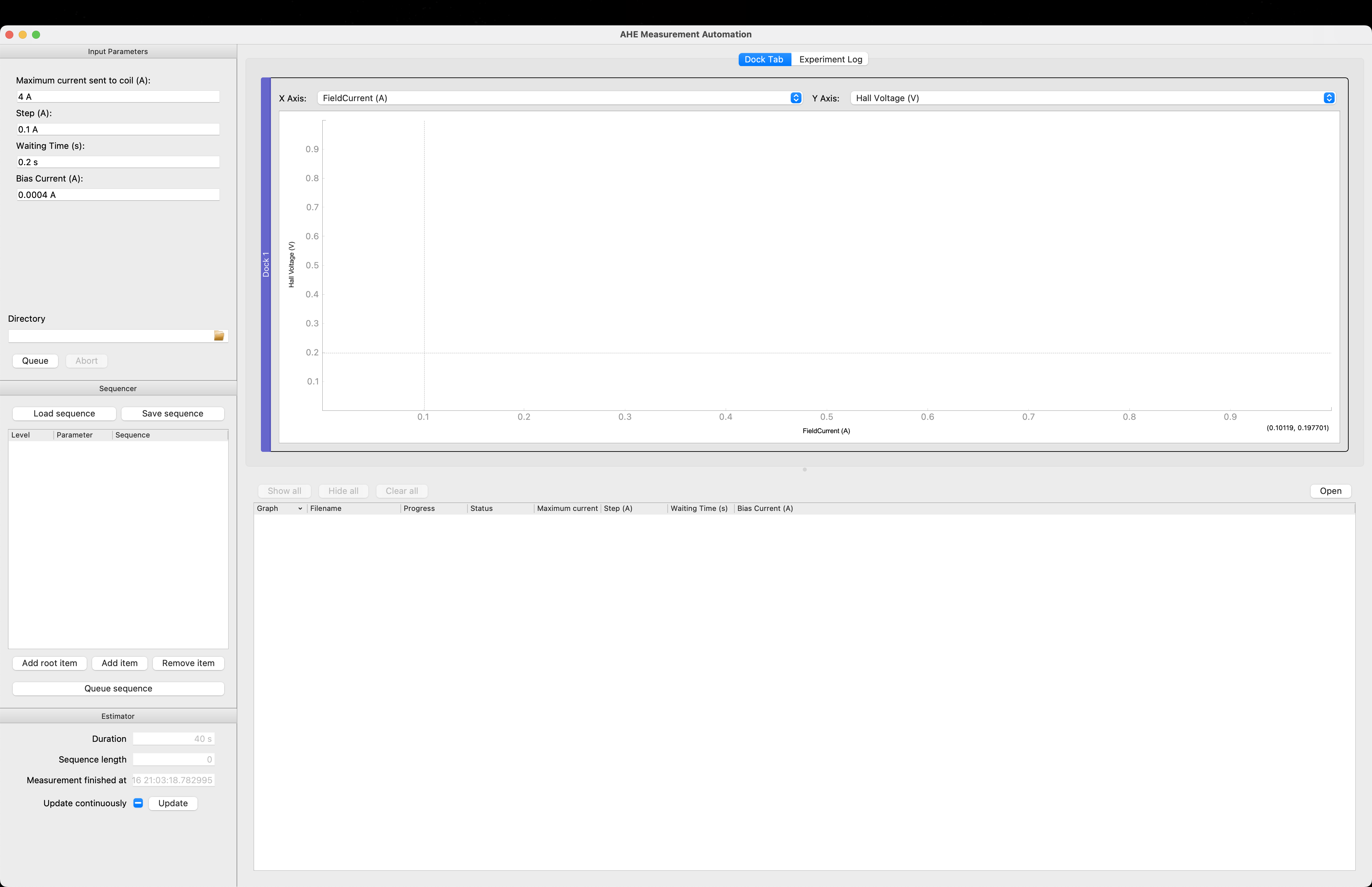
The AHE Measurement System GUI can be divided into 5 Sections
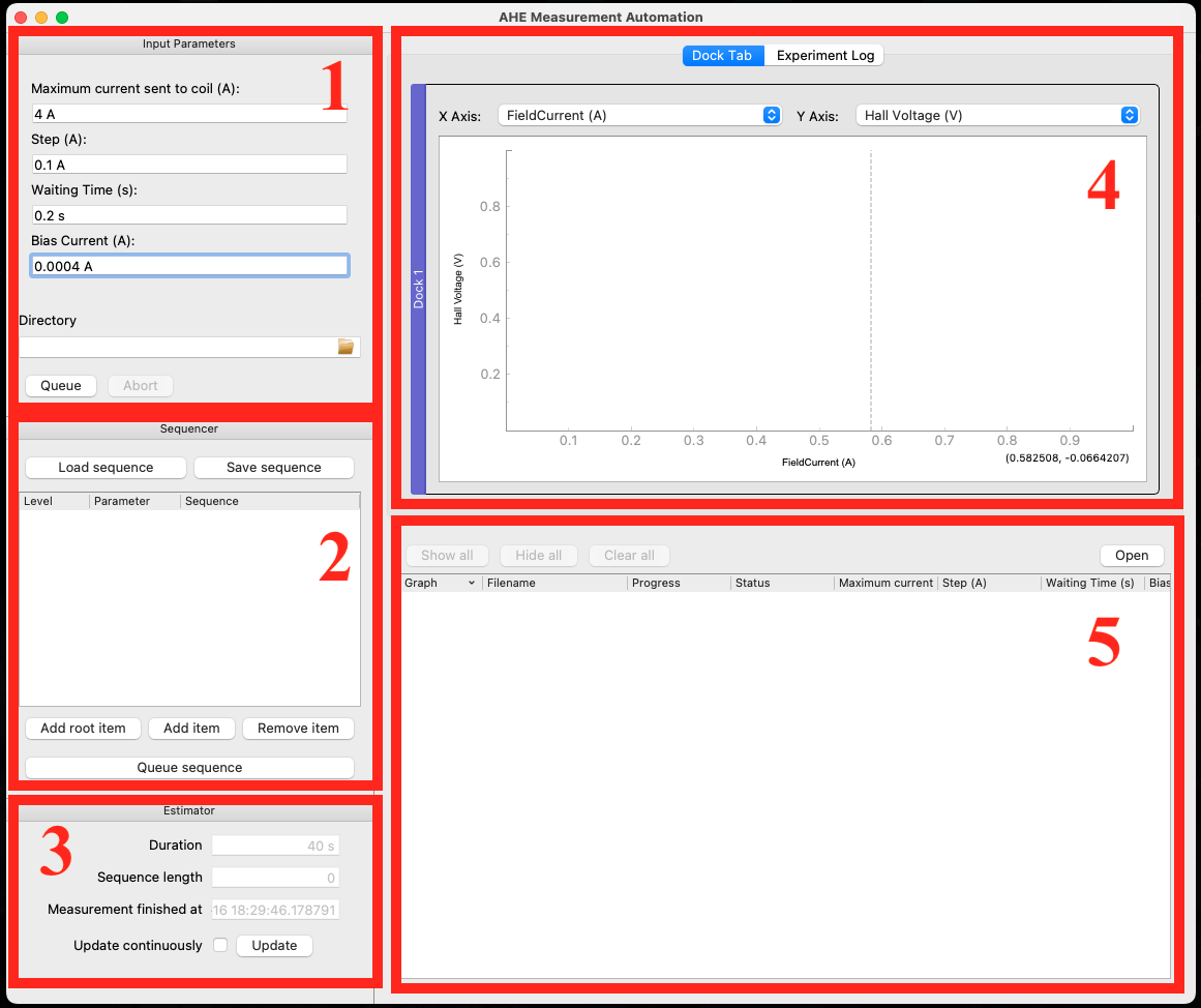
- Section 1: Parameters inputting region
- Section 2: Sequencer generation region
- Section 3: Experimental time estimation region
- Section 4: Live plot region
- Section 5: Experiments Queuer list region
### Section 1:
- Maximum current sent to the coil: DC Current in Ampere sent to the coil to generate the electromagnetic filed.
The electromagnetic field will run towards the positive maximum first to saturate the magnetization, then sweeps though the negative maximum towards again the positive maximum field to generate a hysteresis loop.
Comments: DC Voltage in volt can be also used here, (the code can be modified correspondingly). The efficiency of driving an electromagnet depends on the specific requirements of the application.
For example:
- If the resistance of the coil is known and relatively constant, adjusting the voltage to control the current might be more efficient in terms of power consumption.
- If a constant and stable magnetic field is essential, driving the electromagnet with a constant current may be more efficient.
- In some cases, it might be beneficial to use a combination of voltage and current control to achieve the desired magnetic field characteristics.
- Step (A): the step used to sweep the electromagnetic field
- waiting time (s): time waited after each step is implemented.
- Bias Current (A): constant bias current used for the hall cross bar.
- Directory: folder path to store all the data file generated
### Section 2: Sequencer
Sequencer is provided which allows users to queue a series of measurements with varying one, or more, of the parameters. This sequencer thereby provides a convenient way to scan through the parameter space of the measurement procedure.
### Section 3: Experimental time estimation
In this scenario, the system consistently presents the duration and completion time of an individual measurement. If the Sequencer is utilized, the comprehensive sequence's length, duration, and completion time are also exhibited.
### Section 4: Live plot
A real-time display of the collected data will be shown here.
### Section 5: Experiments queuer
Several experiments with corresponding parameters will be shown here, they will be distinguished by different colour tags.
## Data Example:
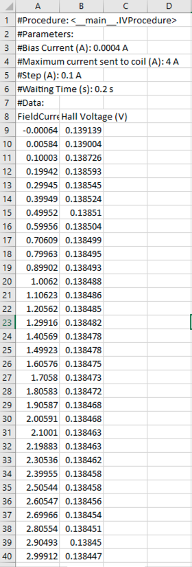
One collected data file is shown as belows:
- all the set parameters
- first column: the coil current collected for the electromagnetic field
- second column: the collected hall voltage
## Sample Video
[AHE measurement sample video](https://icloud.songchen.science/?/AHE%20Measurement/AHE.mp4?p=t)